最新情報 2021.07.20
OpenRAN 5Gのビギナーズガイド(英語記事)
Cellular technology has leapfrogged in the past few decades offering users unparalleled access to on the go services and opening up infinite possibilities. The current standard mobile device now has many applications like navigation, web browsing, instant messaging, e-commerce, payment gateways, streaming content etc. to name a few. With current 3G and 4G networks, a mobile phone is transforming from being a telecommunication device to a full feature computing device. At the same time, the world is waiting with bated breath for 5G networks which will further revolutionize how humans operate in their day to day lives.
Before getting into the details on 5G, let’s first look at a brief evolution of mobile telephony in the last few decades.
A brief history of mobile telephony
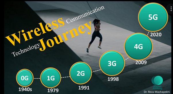
Theoretical foundation of wireless communication was laid in 1890 by Tesla. In 1894, for the first time a wireless signal was transmitted two miles away by Marconi (known as the father of Radio). Over the years, many generations of mobile technologies like 0G, 1G, 2G, 4G and 5G have been developed. ‘G’ stands for ‘Generation’. This generation information appears next to the signal bar on your mobile device and defines the speed of your internet connection. All these technologies over the years and generations are developed based on the telephone network standards.
Zero Generation (0G):
The first generation wireless communication started with 0G technology. In 1971, the mobile phone network was first made publicly available in Finland. The 0G is termed pre-cell phone mobile technology and the first handheld mobile phone was released by Motorola on 3rd April 1973. There are the different types of technologies used in 0G:
- Push to Talk (PTT)
- Mobile telephone system (MTS)
- Improved Mobile Telephone Service (IMTS)
- Advanced Mobile Telephone System (AMTS)
- Norwegian for Offentlig Landmobil Telefoni (OLT)
- Public Land Mobile Telephony (PLMT)
- Mobile Telephony System D (MTD)
First Generation (1G):
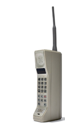
The first generation of mobile network was introduced in the late 1970s (1979) and was fully implemented in 1980s. This was the first cell phone technology. The 1G technology operated at 30 KHz frequency and was an analog technology. The 1G technology phone had poor battery life and voice quality. The security of calls was weak and users experienced frequent call drops. The 1G technology with analog communication continued from 1980s uptil 2G was introduced in 1990’s. The maximum speed for 1G was around 2.4 Kbps.
Second Generation (2G):
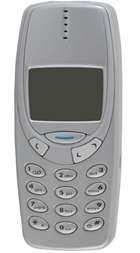
The second generation mobile technology was based on the GSM (Global System for Mobile communication) standard, first introduced in 1991 in Finland. The 2G technology used digital technology, a major departure from the analog based communication used in 1G. 2G technology enabled services like text message, picture messaging and multimedia messages(MMS). It also provided better quality and capacity. The common technology was TDMA (Time Division Multiple Access) based GSM and operated in the network band of 900 MHz to 1800 MHz and data rate of 14.4 kbps. Before switching from 2G to 3G wireless technology which would be a major leap, 2.5G and 2.75G were introduced to fill the gaps.
2.5G (GPRS):
With the introduction of 2.5G and GPRS (General Packet Radio Service) more services such as MMS and Internet communications were introduced. Emails and world wide web access were part of internet communication service. The data rate for GPRS-data was upto 115 Kbps.
2.75G (EDGE): The Enhanced Data rates for Global Evolution (EDGE) technology allowed clear transmission of data and voice up to data rate of 384 Kbps.
Third Generation (3G):

The third generation of wireless technology was introduced in 1998. In the mid 2000s, implementation of HSDPA (High-Speed Downlink Packet Access) began. 3G technology facilitated increase in data transmission at lower cost. The 3G standard utilises technologies like UMTS (Universal Mobile Telecommunications System), CDMA (Code Division Multiple Access) at core network. The 3G network supports bandwidth of 5-20 MHz at a network band of 1800-2400 MHz. With 3G technology, interoperability of different devices became possible and multimedia services became popular. The 3G network combines 2G with a certain new technology to provide faster data rate. Thus, the theoretical maximum speed for 3G is 21.Mbps. Like 2G, many more features were progressively introduced in 3G in order to reduce the gap between 3G and 4G. This evolution in 3G networks are termed 3.5G and 3.75G. With improvement in HSPA (High-Speed Packet Access) and implementation of HSPA+ for 3.5 G and 3.75G, the downlink speed increased to 42 Mbps.
Fourth Generation (4G):

The 4G standard was first commercialized in 2009. The biggest difference between the 4G and 3G is the data rate. With CDMA (Code-division multiple access) and GSM (Global System for Mobile Communications) carriers embracing LTE (Long Term Evolution), 4G LTE was introduced in 2011, and the data rate has improved significantly. The technologies which made it possible are MIMO (Multiple Input Multiple Output) and OFDM (Orthogonal Frequency Division Multiplexing). The max-speed supported by 4G LTE is 1Gbps and this also reduces the latency and congestion in the network. The current 4G devices are backward compatible, i.e they support 2G and 3G technology. The 4G technology enabled HD quality live video streaming.
Fifth Generation (5G):
The fifth generation mobile network is built on 802.11ac IEEE wireless networking standard. 5G is slated to enable services like IoT for smart city, connected cars, healthcare etc. with reduced latency, lower cost, lower battery consumption and higher data rate. The 5G network is based on a high frequency spectrum known as Millimeter Wave Spectrum or Extremely High Frequency. The 5G technology is expected to be 10 times faster than 4G.
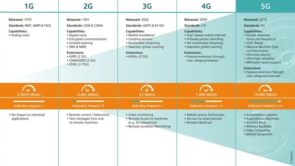
The below image shows the comparison of different technology, impact on industry etc. for different generations of mobile network.
5G technology – Beneath the surface
The 5G communication network is all about high data rate and greater capacity. It is also about providing a rich and reliable experience. Along with 5G deployment that started all over the globe, the new philosophy that is receiving a lot of attention is, OpenRAN. In order to encourage innovation and bring in competition, an entity called O-RAN Alliance is trying to make a 5G network use white box hardware with standardized interfaces. The mission is to reshape the RAN (Radio Access Network) industry for a more intelligent, open, fully interoperable and virtualized mobile network.
What is RAN?
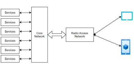
Any cell phone communication uses radio waves to communicate. All the data and voice are converted to digital signal and are then transmitted/received using radio waves through transceivers. Network compromise of two major domains, Core Network and Radio Access Network(RAN). Mobile telecommunication system Radio Access Network (RAN) is the final link between the Core Network and a user device. Communication between the user device (mobile, computer, etc) and core network is established through RAN. The Core Network and User Equipment basically has the Silicon Chip that enables the RAN functionality. The basic building blocks of RAN are Antenna, Radio Unit and Baseband unit(BBU).
What is OpenRAN?
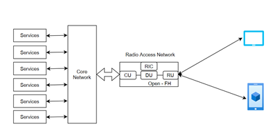
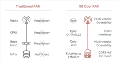
Traditionally a RAN was a single black box and all the internal hardware and software interface used to be from a single vendor. OpenRAN is a term in industry where interpretability of different vendor equipment is possible. In OpenRAN, different functions of base band units (BBU) are split into Centralized Unit, Distributed Unit and Radio Unit with open fronthaul (Open-FH) interface between them.
There are two major organizations that define the OpenRAN standard, namely O-RAN Alliance and Telecom Infra Project (TIP). O-RAN Alliance defines the openness principle for OpenRAN which allows smaller players in the market to come up with products. TIP on the other hand provides OpenRAN a totally disaggregated approach built entirely on cloud native principles and virtualized RAN. Thus, the organizations together define the OpenRAN architecture that enables interoperability of products and solutions from different vendors.
OpenRAN 5G Architecture
The OpenRAN 5G architecture is fully compliant to 3GPP (3rd Generation Partnership Project) standard technical specification TS38.401. Specification completely disintegrates the Baseband Unit in two major splits, namely Distributed Unit (DU) and Centralized Unit (CU). Thus, the building blocks of the decomposed Baseband Unit are,
- Radio Unit (RU)
- Distributed Unit (DU)
- Centralized Unit (CU)
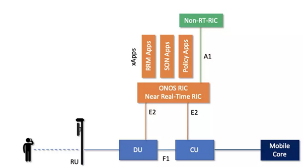
- Near-Real Time RAN Intelligent Controller (RIC)
- Service Management and Orchestration Framework(SMO)
- O-Cloud
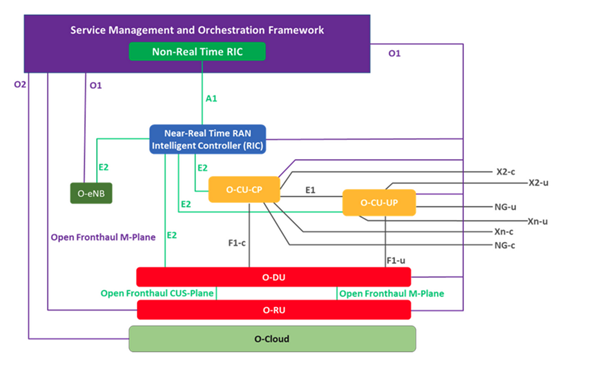
The study of 5G New Radio had a learning that providing the split upto gNB between DU and CU would provide more flexibility. In the 5G radio node gNB is the logical node. What was NodeB in 4G is gNB or gNodeB in 5G, where g stands for “next-generation”.
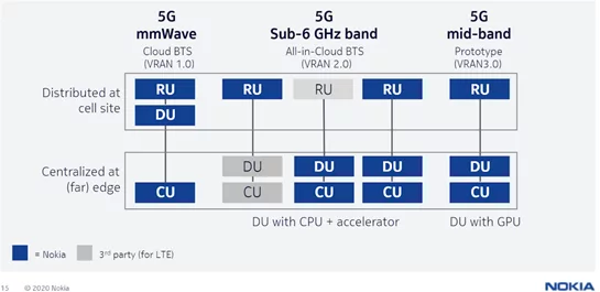
Thus, with logical nodes (gNB) and interoperability of software and hardware components it provides cost effective deployment of the network. Nokia, on the other hand, believes that the only valid split is between RU and DU. This split may be different depending on use case and implementation. In any case, it provides a cost effective interface between hardware and software.
Radio Unit (RU)
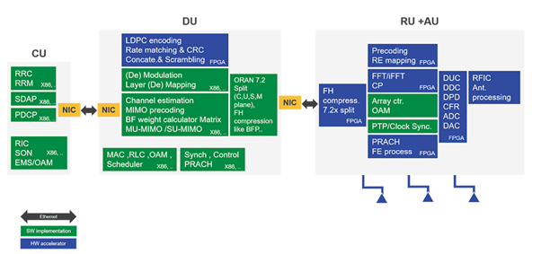
The RF frontend, digital frontend, LowPHY layer, Ethernet/MAC PHY fronthaul for baseband processing and digital beamforming functionality is part of RU. In the legacy unit the PHY layer is part of Baseband Unit (BBU), but for 5G OpenRAN, it is split into LowPhy and HighPHY. The LowPHY processing basically consists of FFT, IFFT, digital beamforming, cyclic prefix addition. These modules are time consuming modules, keeping it part of RU reduces latency in 5G OpenRAN architecture.
Distributed Unit (DU)
The DU is between Radio Unit and Centralized Unit, and typically is close to RU. It is responsible for performing the HighPHY, Ethernet MAC, OAM operation. The logical connection between gNB-DU and gNB-CU is through a F1 interface. This interface is in accordance with 3GPP F1 interface specifications. The F1 interface has two higher level splits, F1-C and F1-U depending on control plane and user plane functionality respectively. It spearete separates the Transport Network Layer and Radio Network layer. It is responsible for the real time layer 1 (L1, physical layer) and layer 2 (L2) scheduling and data link functions. Depending on availability of fronthaul interface, the DU’s server and relevant software is hosted onsite itself or can be hosted in an edge cloud. In case of intense processing such as FFT and IFFT, DU can co-exist with CU which helps in low-latency and real-time interface management.
Centralized Unit (CU)
The Centralized Unit helps in load sharing between different DU and RU. Through the midhaul interface CU controls the operation of DU. Each CU can be connected to a single or multiple DU. Thus, depending on single or multiple DU, a corresponding number of gNB are supported. For each gNB (logical node), the connection between CU and DU is via the Fs-C and Fs-U interface. The OpenRAN split architecture enables distribution of protocol stacks between CU and DU, thus load sharing between CU and DU. CU performs a non-real time operation, i.e., higher L2 and L3 processing.
5G RAN Functional Spilt
From the 3GPP’s 5G-NR RAN specification there are a total of 8 functional split options available. Service providers would align to one of the split architectures depending on the requirement and infrastructure. This will help service providers to take advantage of disaggregated hardware and software approaches. But with tough fronthaul requirements to meet, after discussion, 3GPP defined two 5G-NR split architectures in addition to the monolithic one. These are,
- Option 2 : High-level CU and DU split
- Option 7.2 : Low-level split for low-latency communication
O-RAN Alliance and Small Cell Forum (SCF) also proposed specification for 5G functional split further enhancement to the base design.
- Split 2: RRC(Radio Resource Control)/PDCP (Packet Data Convergence Protocol) Split
- Split 6: MAC/PHY layer split
- Split 7.2x: Low PHY/High PHY split
- Split 8: PHY-RF split
The split options will be advantageous and provide gain only when complete end-to-end network is considered while developing.
O-RAN Alliance split 7.2x
The O-RAN Alliance split 7.2x has two variants.
- Split 7.2a : Precoding part of O-DU and Beamforming onward part of O-RU
Split 7.2b : Precoding onward part of O-RU.
Conclusion
Organizations like 3GPP, O-RAN Alliance, Telecom Infra Project (TIP) and Small Cell Forum (SCF) will come up with enhancements to the OpenRAN Architecture. The service provider should consider all the specifications and use cases which meet the requirements in the best possible way for their 5G development and deployment. The disaggregated and split architecture would be cost effective and thus enable wider deployment and more users enjoying services offered by 5G technology.
References
- https://www.o-ran.org/
- https://www.rcrwireless.com
オススメの記事